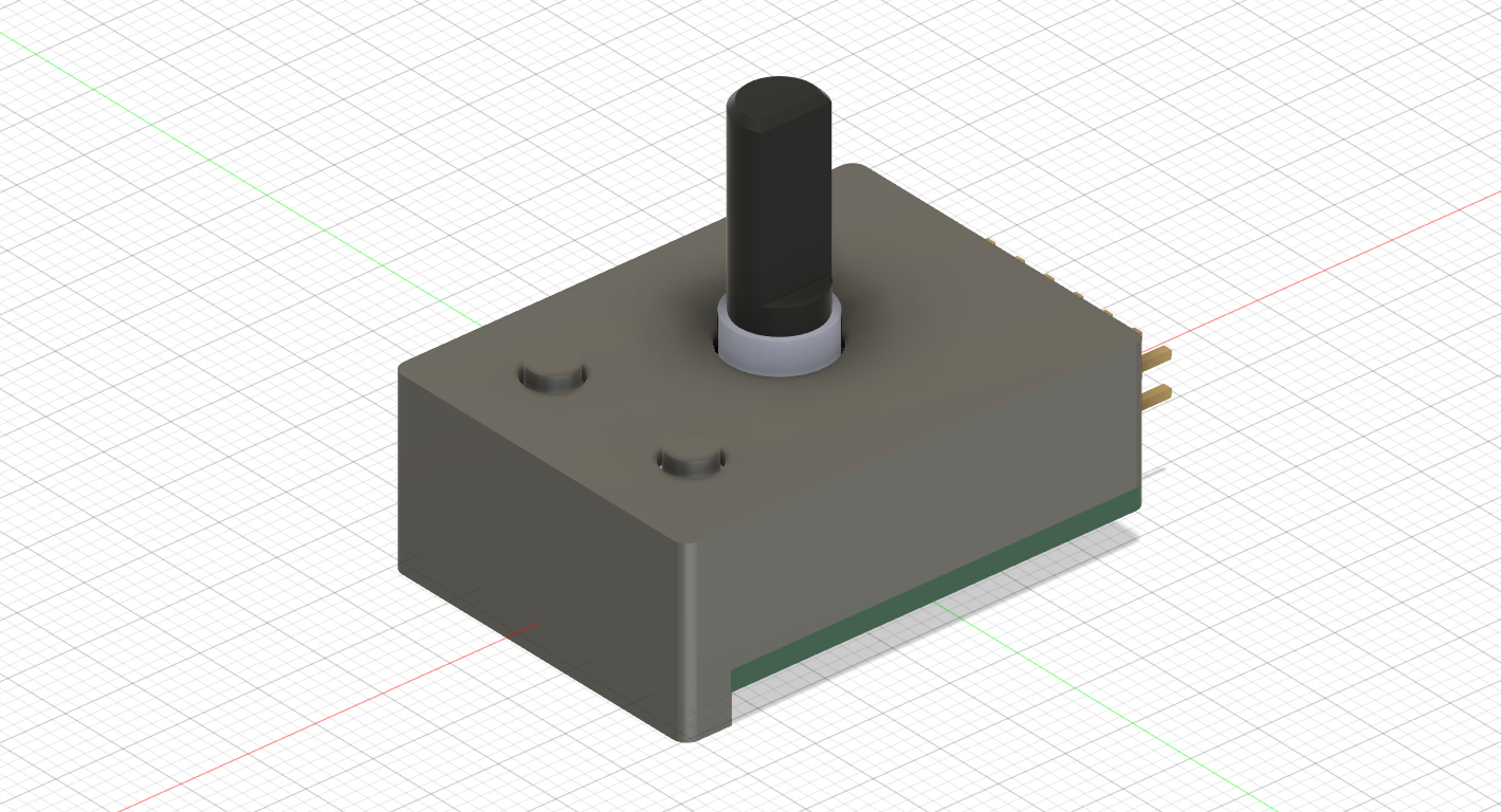
A custom expansion module featuring an EC11 rotary encoder and two tactile buttons for menu navigation and UI control. Built with KiCad, Fusion 360, and Rust
Firmware was definitely the most time-consuming part. Rust is still pretty foreign to me, so I spent a good chunk of time going through the xpanse-api docs and reading through example drivers to figure out how inputs are registered.
I set up the driver struct and implemented DriverMeta with my resistor values, then mapped GPIO0 and GPIO1 to the rotary encoder interface, GPIO2 and GPIO3 to buttons A and B, and GPIO4 to the encoder's center switch.
Once the driver was compiling in VSCode, I wrapped everything up by organizing the GitHub repo. I put together the file tree with /pcb, /cad, and /firmware folders, generated the live KiCanvas and Fusion 360 share links, built the BOM.csv, and wrote the README.
1h
CAD Enclosure
Next up was designing the case in Fusion 360. I imported the PCB export as a STEP file so I had exact positions for the encoder shaft, the two push buttons, and the board mounting holes.
I sketched out an outer shell around the board template and extruded the walls to fit the single module bay. The trickiest part was getting the cutouts right so the encoder shaft and tactile buttons sit flush through the top plate without rubbing against the edges.
I added two mounting posts on the bottom for M2 screws to hold the PCB tight inside the case so nothing flexes when you press the buttons down.
Once the alignment looked good in CAD, I exported the .f3d source file and standard .step assembly.
1h 30m
Schematic, PCB, and Setup
So I wanted to build a simple controller module with a rotary encoder and two buttons for quick menu navigation on the console. I started by cloning the base module template from the hackxpansion repo to get the board dimensions and header pins right.
After that, I opened KiCad to set up the schematic. I picked an EC11 encoder with an integrated push switch and two standard 6x6 tactile switches. Routing was pretty straightforward since it's just routing GPIO lines back to the main header along with the MD0 (1k) and MD1 (36k) identification resistors.
Once the schematic was done, I switched over to the PCB layout. I kept it as a simple 2-layer board with ground fills on top and bottom to keep things stable. Fitted everything into the single slot constraints, ran the traces, and exported the Gerber files and .kicad_pcb.